|
For a long time, I never really understood the differences between the oxygen
sensors used on the Vortec family of engines. Some sensors have flat
connectors, some square, some white, some black, etc. I will attempt, to
explain this in the best of my ability. This is completely from my own
research, looking at schematics, wiring harness, service manuals, parts stores,
internet search. I am going to concentrate on what the differences in the
sensors are, and how they are wired.
For what a oxygen sensor is and does, I highly recommend doing a Google
search for ''o2 sensor wiki''.
The first few years of the Vortec engine, 99-02, there could have been
a few different types of o2 sensors. GM refers to these in the factory
service manual as either CASE GROUNDED or ISOLATED GROUND type sensors. If
you go to a parts store, they may ask if it was Canada, USA or Mexico built, or
the starting VIN#. You can determin where it was built, IF you have the
VIN #. Go here: GM
VIN Information The VIN cards here have both CAR and TRUCKS.
Trucks are on second page. Typically the very first digit in the VIN will
tell you the location built.
1 or 4 = US Built, 2 = Canadian Built, 3 = Mexico Built
2001,2002 6.0L uses a different connector then
4.8/5.3L engines. Scroll to bottom of this page for more info on that.
For the most part,
this info pertains to 4.8/5.3L engines only.
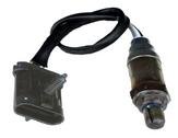
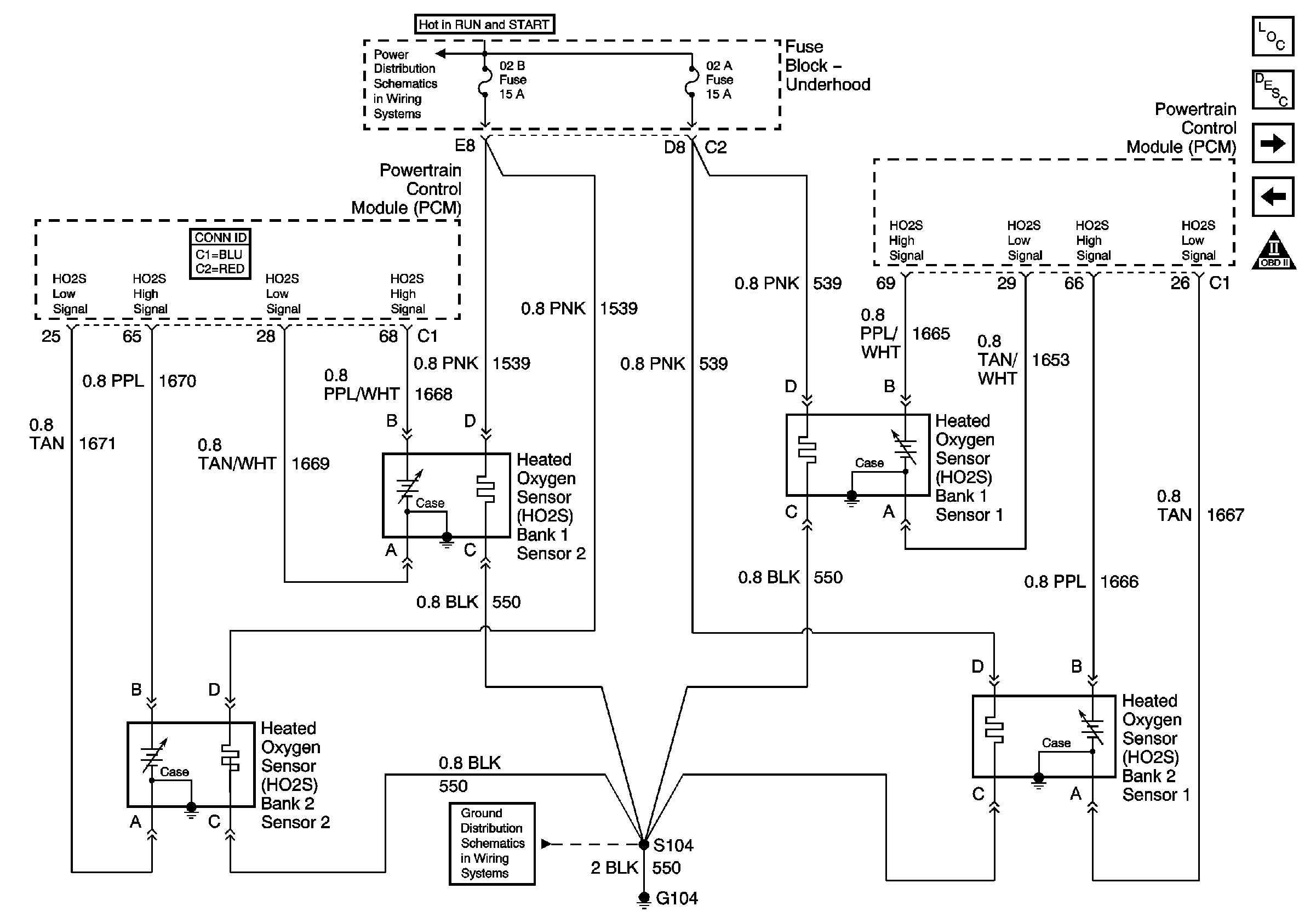
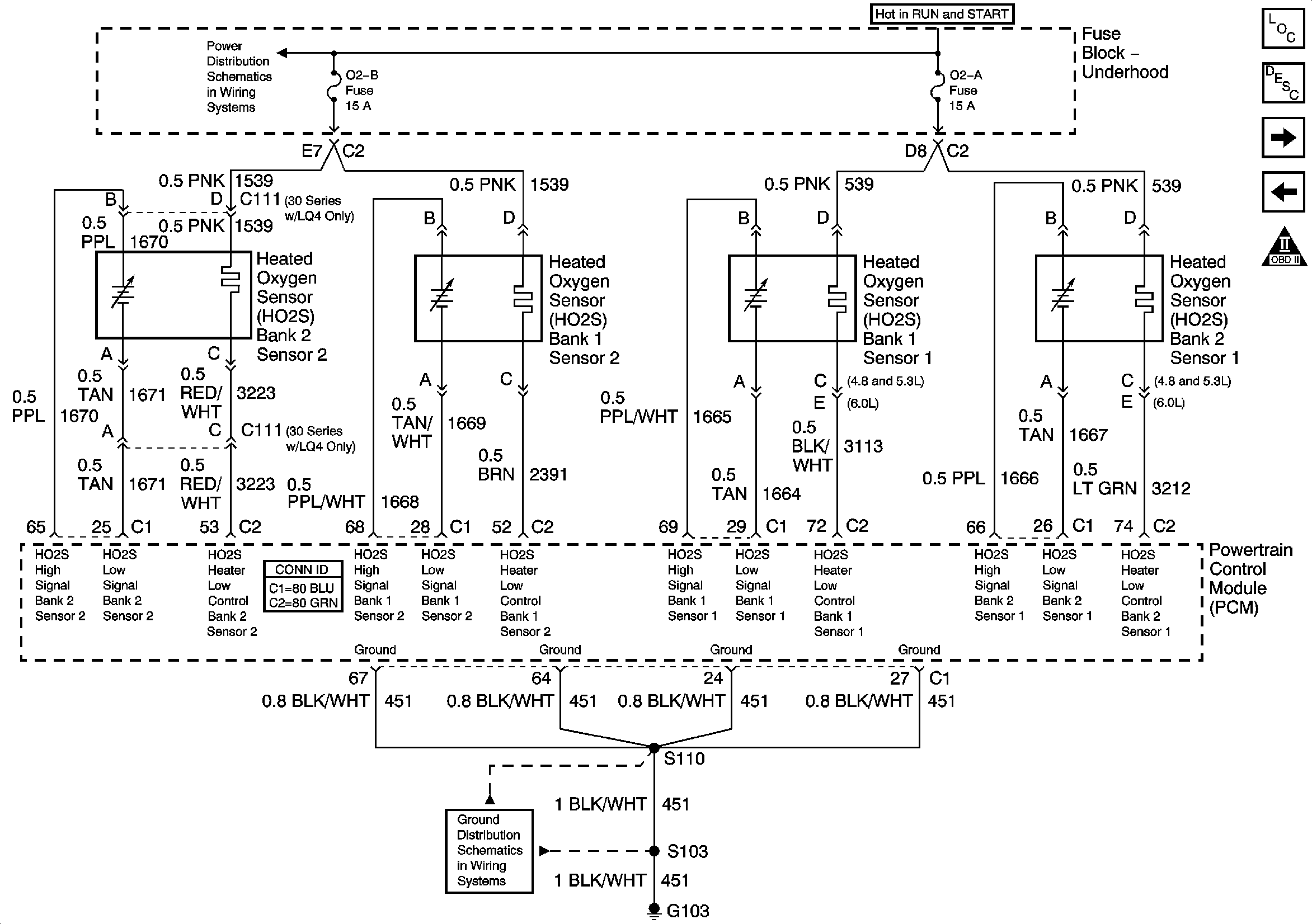
CASE GROUNDED sensors: This type of sensor uses the body of the oxygen
sensor its self, for a ground. The body of the o2 sensor is connected to
the TAN wire going to the PCM. A single un-interrupted wire goes from the
sensor directly to the PCM. I'm fairly certain, that ALL 1999 4.8/5.3
trucks no matter where they were built, used this type, as well as 2000-2002 US
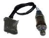
and Mexico built trucks. The sensor has a FLAT 4 pin BLACK connector
for the before cat o2 sensors. I THINK the after cat o2
sensors had a SQUARE 4 pin BLACK connector.
|
|
|
|
case ground before cat o2
|
|
|
|
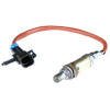
case ground after cat o2
|
|

|
|
case grounded schematic
|
|
|
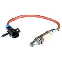
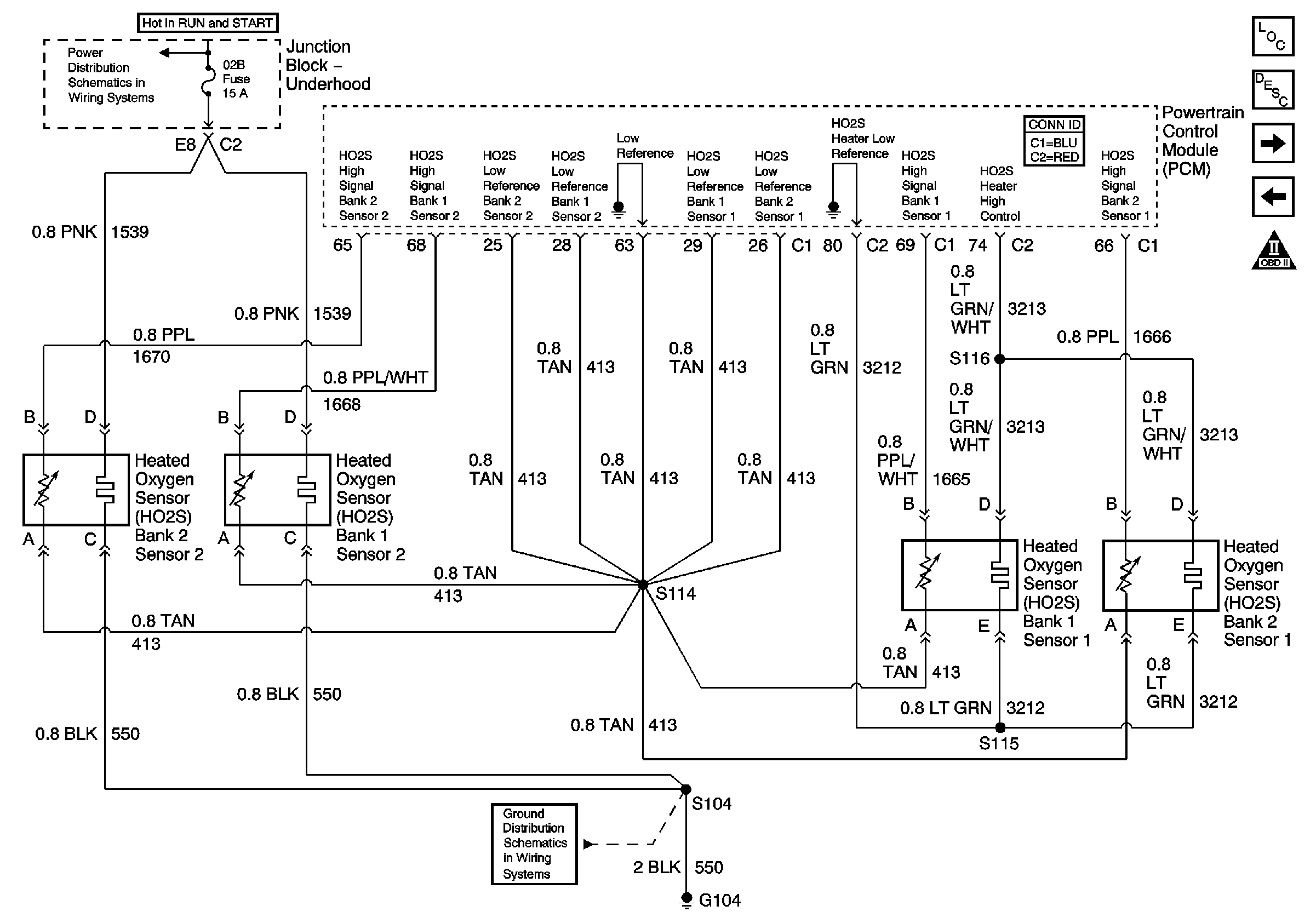
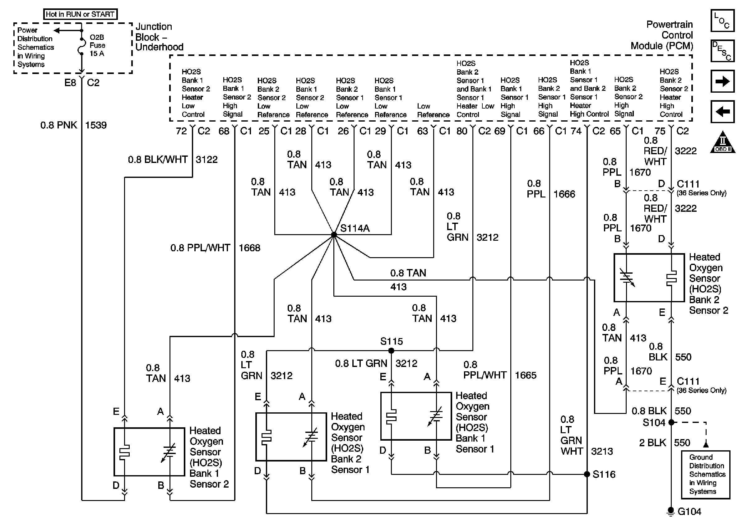
ISOLATED GROUND sensors: This type of sensor, gets its ground FROM the PCM.
The body of the sensor IS NOT connected to the TAN wire going to the PCM.
So the TAN wires need grounded from another point. All TAN wires going
into a splice pack, located inside the wiring harness. This splice is
located on the part of the harness, that goes down the back of the intake, going
toward the transmission connector. It is about 6-8 inches down from the
top of the intake. Tan wires from each of the 4 sensors enter the splice,
and 5 TAN wires go to the PCM. 4 of the TAN wires go to the SAME location
as the case ground schematic above, but a 5th wire to the PCM goes to BLUE PCM
connector pin 63. Pin 63 is a Low Reference (or ground) This simply gives
a better ground path for the oxygen sensors. The sensor has a SQUARE 4
pin WHITE connector for the before cat o2 sensors. I THINK the after cat
02 sensors had a SQUARE 4 pin WHITE connector as well.
|
|

|
|
isolated ground befor cat o2
|
|

|
|
isolated ground schematic
|
|
|
6.0L Info: Starting in 2001, the 6.0L engines could have had either
CASE grounded or ISOLATED ground sensors, or a mix of both. On these, the
before cat o2 sensors were a tri-angle shape, with 5 pin locations, using only
4. The after cat o2 sensors were square, 4 pin. Unsure on colors per
year, but I have seen these in white and black. The before cat o2 sensors
in these years, had heater ground circuits AND the heater power circuits are controlled by the PCM.
2003+ all used ISOLATED ground sensors, there is no longer an option
for the CASE GROUND. Also the need to have the splice pack with all the
tan wires is no longer needed, as the 4 TAN pin locations in the PCM are now
internally grounded, and don't have to be linked to pin 63. This is
IMPORTANT if you want to use a 2003+ harness with an older 99-02 PCM.
See HERE for specific info on wiring that.
Here are some useful schematics
|
|

|
|
2001-02 4.8/5.3 with case ground sensors
|
|

|
|
2001-02 4.8/5.3 with isolate ground sensors
|
|

|
|
2001-02 6.0L with case & isolate ground sensors
|
|

|
|
2001-02 6.0L with isolated ground sensors only
|
|

|
|
2001-02 8.1L oxygen sensors
|
|
|
|

|
|
2003+ 4.8/5.3/6.0 oxygen sensors
|
|

|
|
2003 8.1L oxygen sensors
|
|
|
|