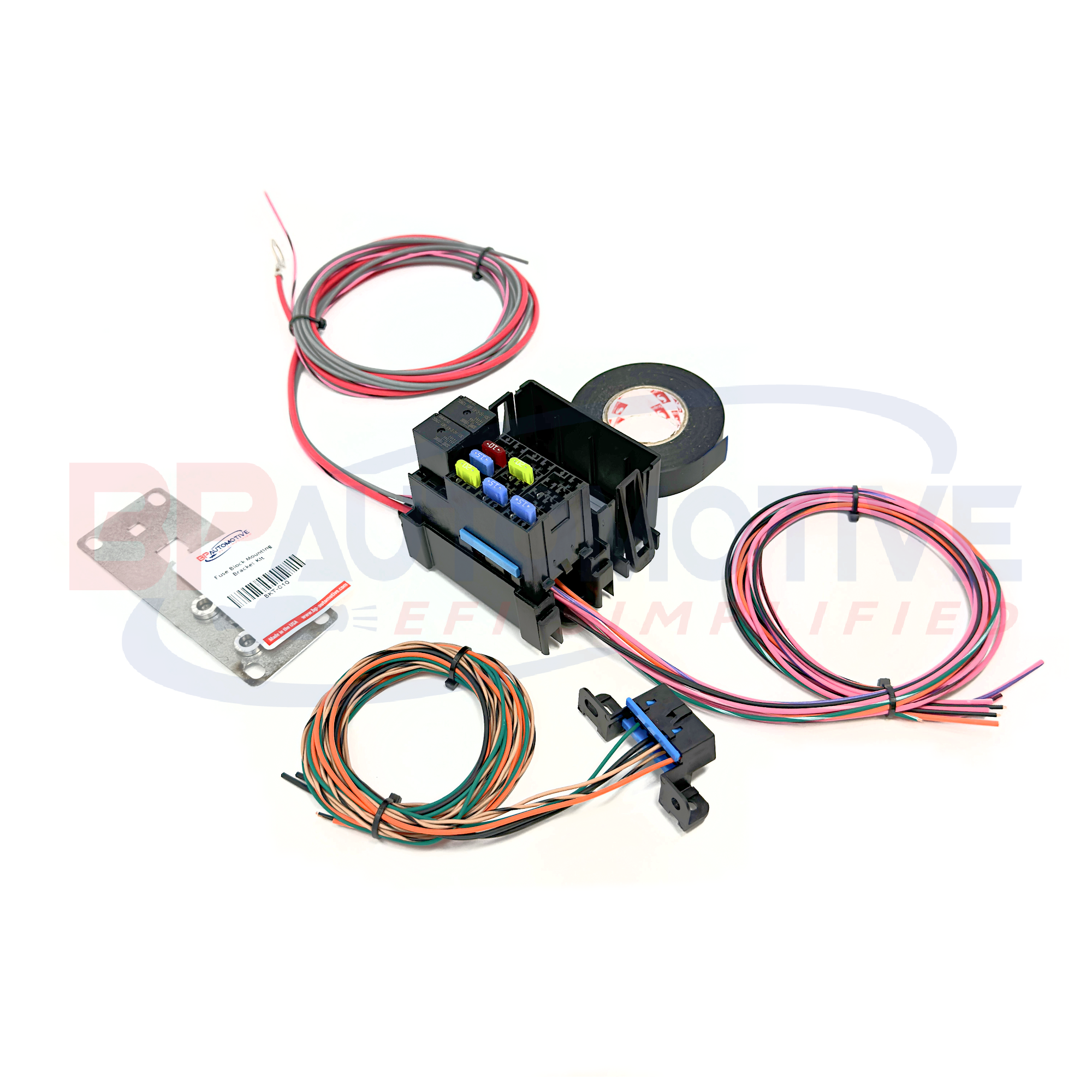
A lot of these parts is previously listed are harder to find now in 2025. I highly recommend a premade fuse block such as one from BP-Automotive. The DIY fuse block kits will come with diagnostic port, prebuilt fuse block with circuits for pcm, injectors, coils, trans, maf, o2 sensors. There is another kit available with fan relays. I recommend going to BP Site and check out what they have.
https://bp-automotive.com/product-category/diy-kits/
Here I will outline building your own fuse block and attach relay sockets. This is a general guide that will work for most any wiring harness. I use this same basic setup for LT1, LS1, Vortec Trucks etc.
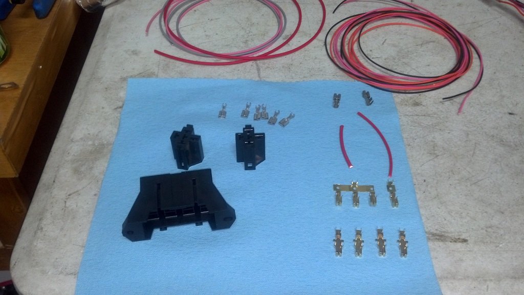
First off, the parts you will need to build the fuse block and OBD2 Diagnostic Port.
| OBD2 Diagnostic Port Parts | Vendor | Part# | Qty Needed |
| OBD2 Port Plastic Connector, 16 Pin | www.mouser.com | 829-12110250 | 1 |
| Terminals - for OBD2 port | www.mouser.com | 829-12129373 | 4 |
| Terminal Lock - secures terminals | www.mouser.com | 829-12160437 | 2 |
| Lamp (for check engine light) | www.allelectronics.com | check lamps/indicators, inventory changes | |
| Fuse Block & Relays | Vendor | Part# | Qty Needed |
| Fuse Block Housing kit (terminals included) | www.rockauto.com | 85668 | 1 |
| Relay Socket | www.allelectronics.com | SRLY-2 | 2 |
| Relay 30 Amp | www.allelectronics.com | RLY-351 | 2 |
| Relay Terminal 14-18 AWG | www.mouser.com | 571-42238-2 | 8 |
I have found that AUTOZONE can order you the fuse block, with terminals for $5.00 part# is 85668. This is a Dorman part. From www.rockauto.com its less then $3.00.
|
||||

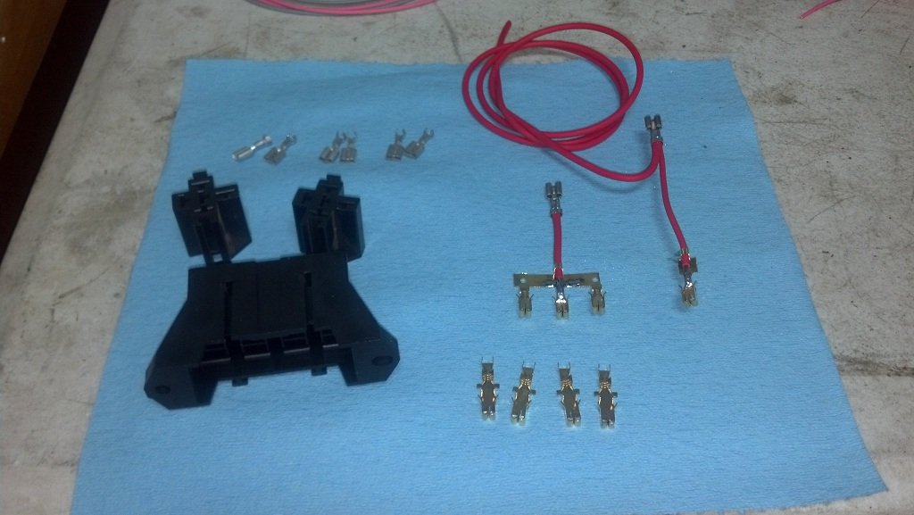
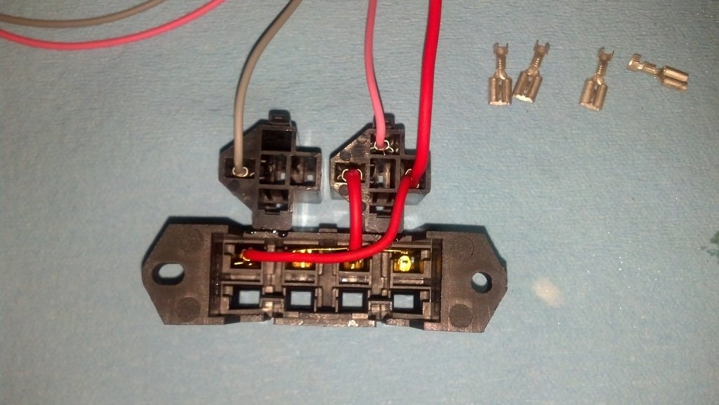
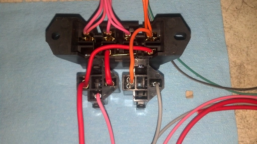
FUSE BLOCK WIRING
The relay sockets from allelectronics will have short wires in them, with terminals. DO NOT use these, you can insert a small screw driver in the slot on the top and bend the tab, and remove them. Order new terminals. The stock wires on these relay sockets are not up to the current needs of the fuse block. Also, these sockets are the only ones I can find, that will slide onto the side of the fuse block.
Order extra terminals incase you need to re-do something, for OBD2 port, Relay sockets, Fuse holder, etc, they are not expensive, $0.10 to $0.25 each or so. I always crimp AND solider all my connections.
Hold down the SHIFT key on your keyboard when you click the picture to see a large version of the picture in a new window.
|
|
|
|
|
|
|
|
|
|
|
|
|
||


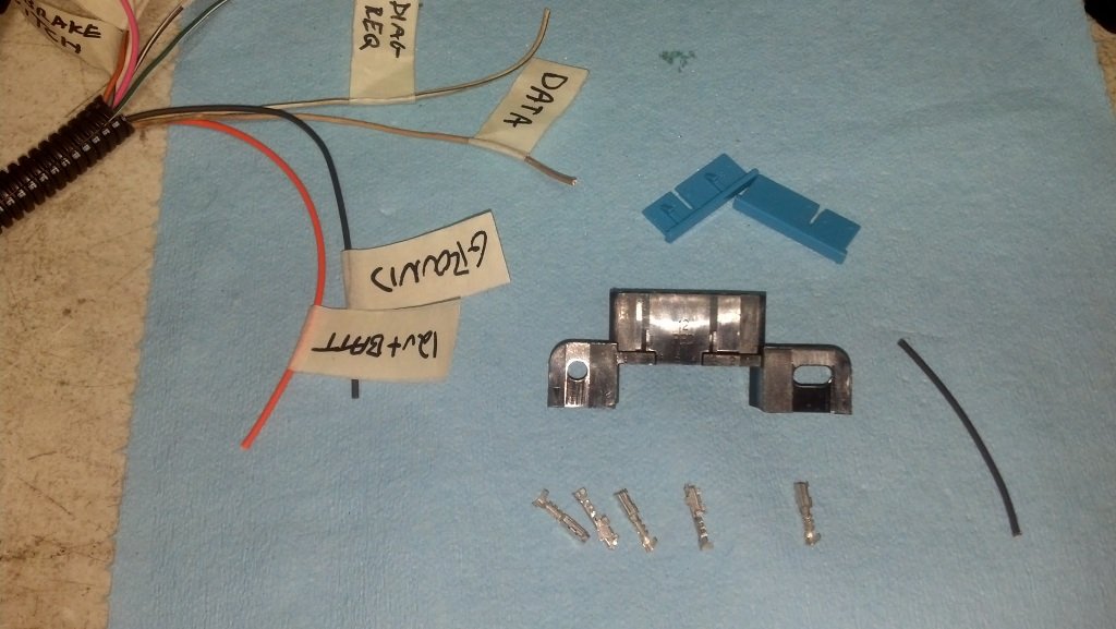
OBD2 DIAGNOSTIC PORT WIRING
All OBD2 port's for LS1, Vortec Truck are the same.
Pin 2. - Serial Data - FROM the PCM.
Pin 4 & 5 - GROUND - Usually only pin 5 is needed, however some scan tools/code readers will need GROUND on pin 4 as well.
Pin 16 - 12v+ BATTERY - Power from 12v+ Battery source.
OBD2 LT1, 96-97 ONLY will have additional wiring to OBD2 port.
Pin 6 - Diagnostic Request/Field Output Enable
Pin 9 - UART Serial Data
1995 LT1 used an OBD2 port, but were not OBD2 vehicles. These did not have a Serial Data on Pin 2. These used pin 9.