Here you will find wiring harness information for the Vortec 8100 Engine. This particular post is for the 2001 model C/K 2500 or 3500 Chevy Pickup. C2 Underhood fuse block connector is the same as vortec 4.8/5.3/6.0 for each year. Go here for the underhood fuse block connector information. However, see bottom of this page for C100, C152 info for the 8.1L harness.
Engine Controls Schematics - see pictures below chart
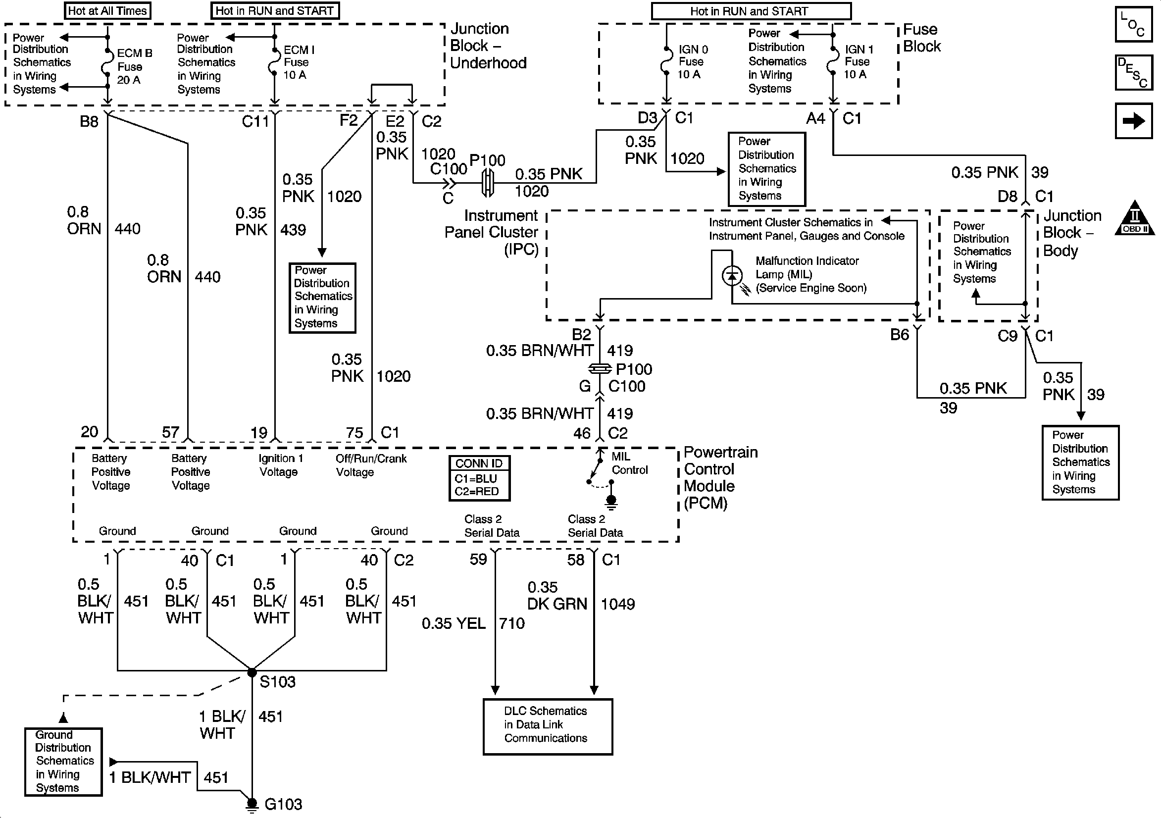
| Figure 1: | Power, Ground, and IPC |
| Figure 2: | PCM, ENG 1 Fuse, Engine Coolant Temperature (ECT) Sensor, and MAP Sensor |
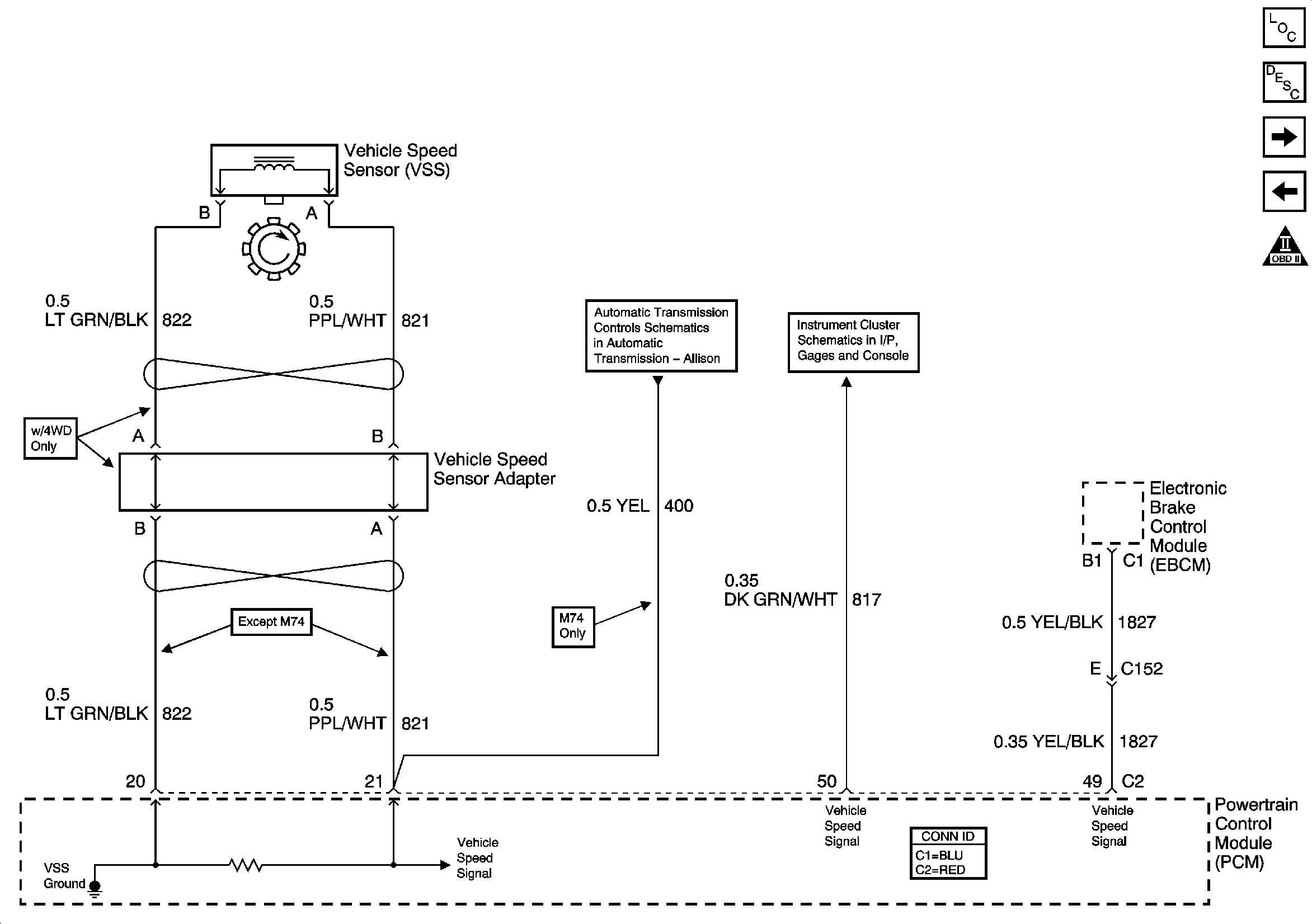
| Figure 3: | Engine Data Sensors - VSS |
| Figure 4: | INJ B Fuse, Ignition Coils, and PCM |
| Figure 5: | INJ A Fuse, Ignition Coils, and PCM |
| Figure 6: | Camshaft Position Sensor (CMP), Crankshaft Position Sensor (CKP), and Knock Sensors |
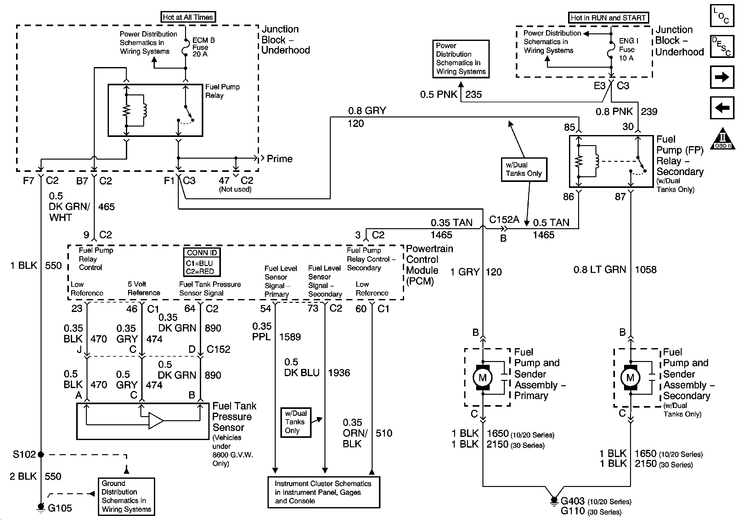
| Figure 7: | Fuel Pump Relay, Fuel Tank Pressure Sensor, Primary and Secondary Fuel Pump and Sender Assemblies |
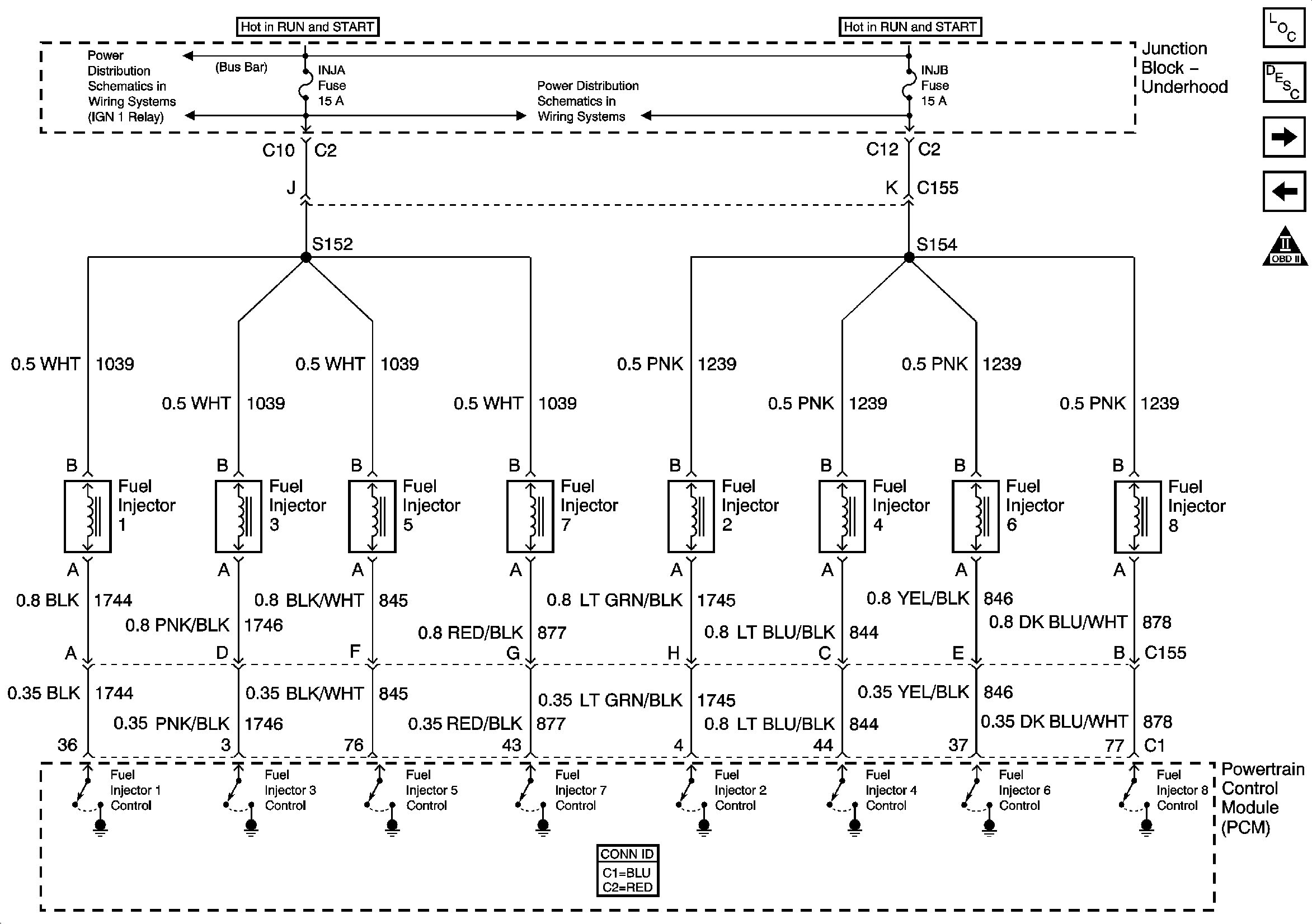
| Figure 8: | INJ B Fuse, INJ A Fuse, Fuel Injectors, and PCM |
| Figure 9: | Secondary Air Injection (AIR) |
| Figure 10: | Heated Oxygen Sensors (HO2S) |
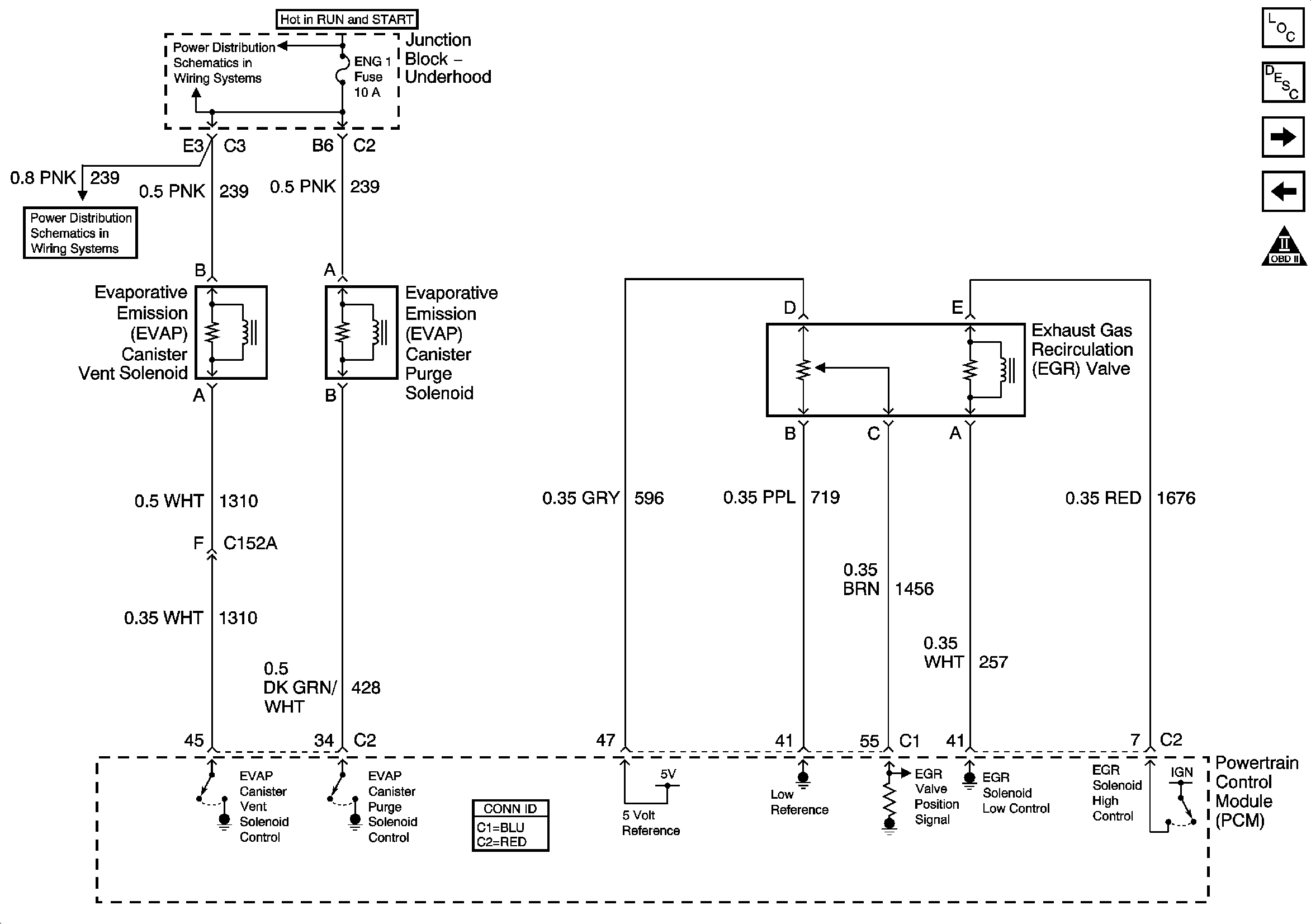
| Figure 11: | Evaporative Emissions (EVAP) Canister Purge and Vent Solenoids and Exhaust Gas Recirculation (EGR) Valve |
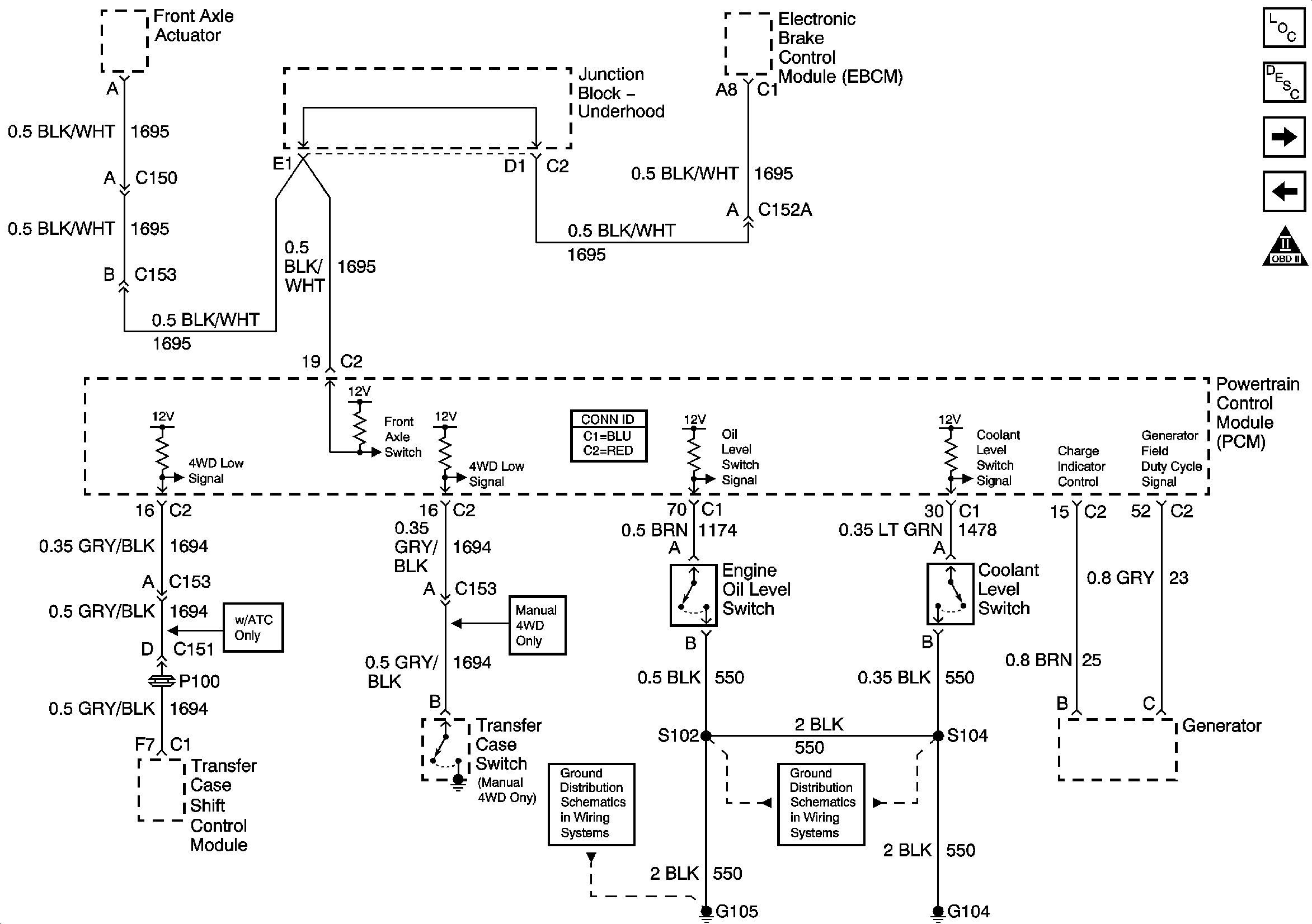
| Figure 12: | Coolant Level Switch, Engine Oil level Switch and Generator |
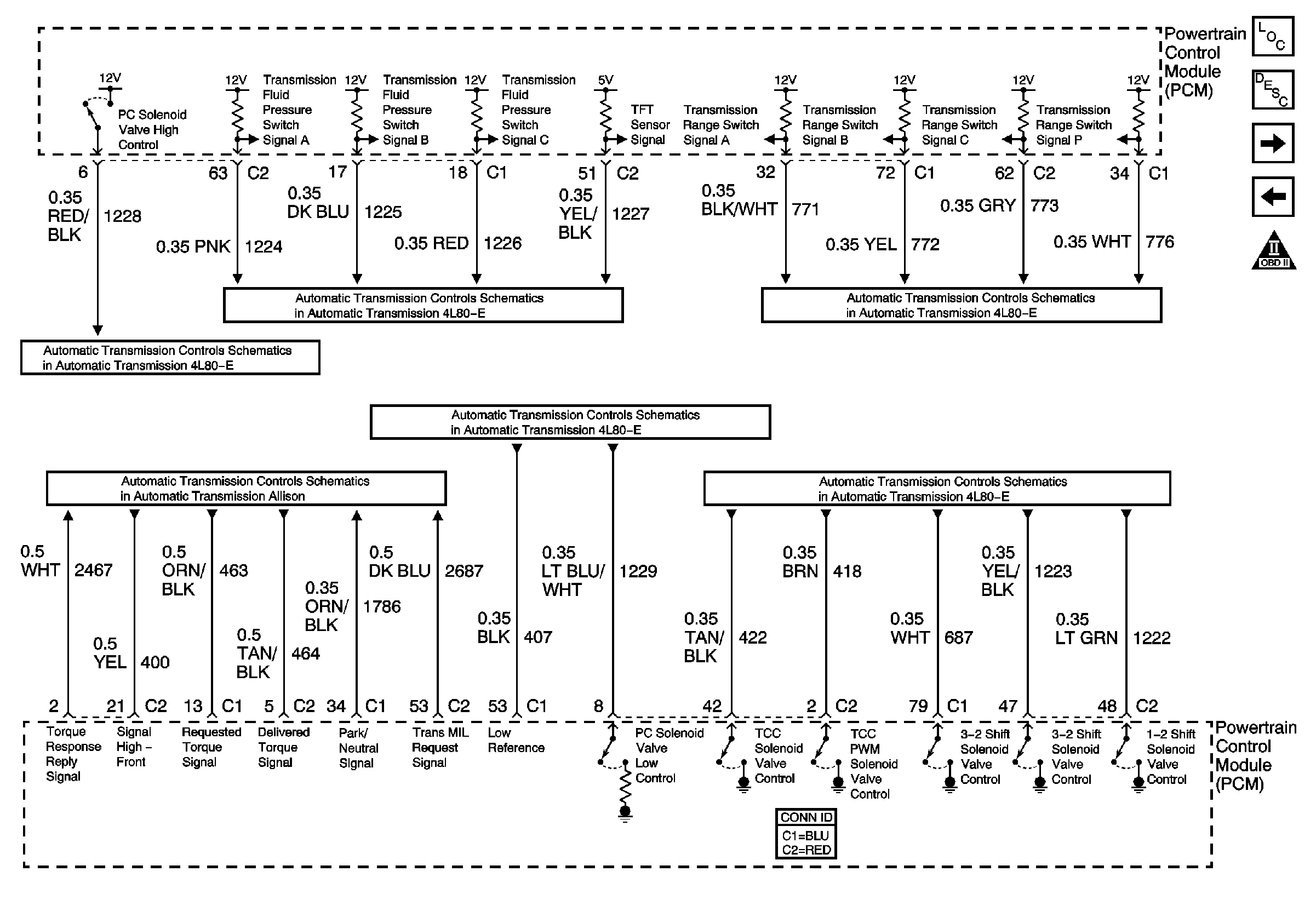
| Figure 13: | Automatic Transmission Controls References |
| Figure 14: | A/C High Pressure Switch, A/C Low Pressure Switch, and PCM |
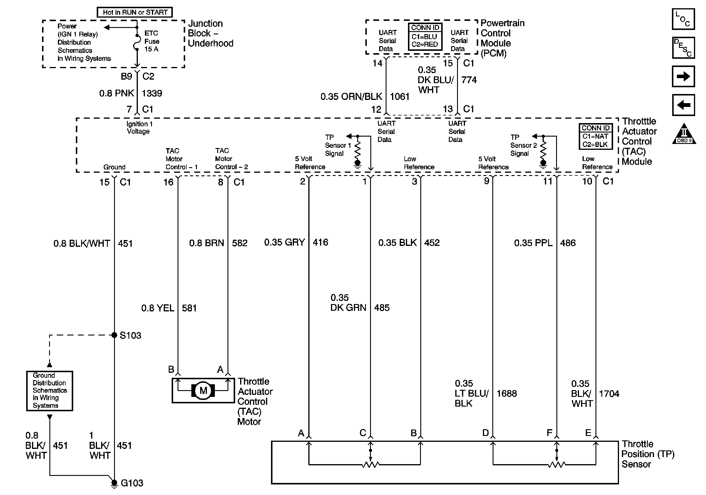
| Figure 15: | Throttle Actuator Control (TAC) Module, ETC Fuse, Throttle Position Sensor |
| Figure 16: | Cruise Control ON/OFF Switch, STOP LPS Fuse, and Accelerator Pedal Position(APP) Sensor |
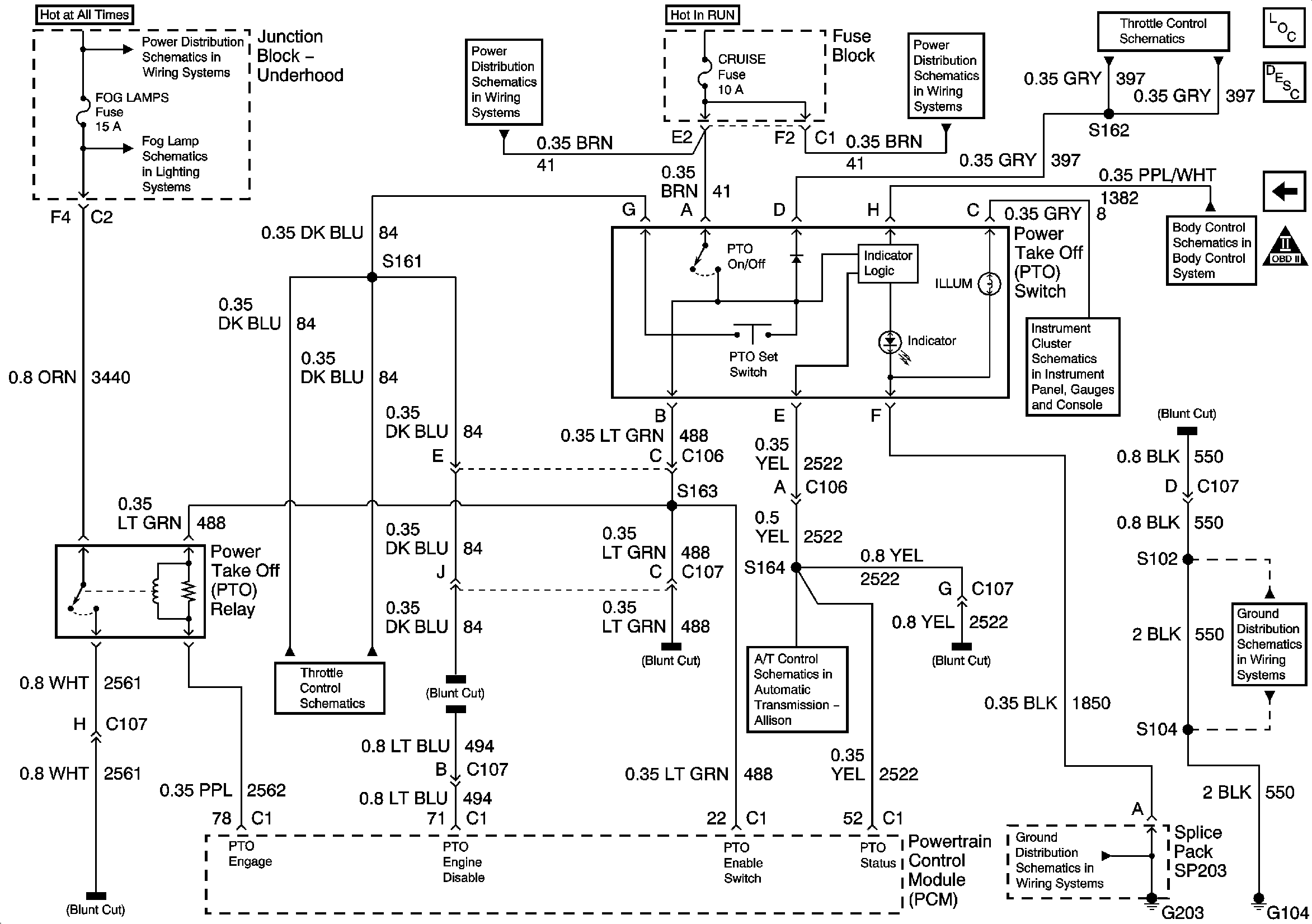
| Figure 17: | Power Take Off (PTO) Switch, Power Take Off Relay, and PCM |
|
|
|
|
|
|
|
|
|
|
|
|
|
|
|
|
|
|||


C100, C152 Information
 |
|
||||||||||||||
|---|---|---|---|---|---|---|---|---|---|---|---|---|---|---|---|
| Connector Part Information |
|
Connector Part Information |
|
||||||||||||
| Pin | Wire Color | Circuit No. | Function | Pin | Wire Color | Circuit No. | Function | ||||||||
| A | DK BLU | 84 | Cruise Control Set/Coast Switch Signal (Electronic Throttle Control) | A | DK BLU | 84 | Cruise Control Set/Coast Switch Signal (Electronic Throttle Control) | ||||||||
| A | LT BLU/BLK | 396 | Cruise Control Engaged Signal | A | LT BLU/BLK | 396 | Cruise Control Engaged Signal | ||||||||
| B | WHT | 1294 | Variable Effort Steering Actuator Supply Voltage | B | WHT | 1294 | Variable Effort Steering Actuator Supply Voltage | ||||||||
| C | PNK | 1020 | Off/Run/Crank Voltage | C | PNK | 1020 | Off/Run/Crank Voltage | ||||||||
| D | DK GRN/WHT |
817 | Vehicle Speed Signal | D | DK GRN/WHT |
817 | Vehicle Speed Signal | ||||||||
| E | PPL | 420 | TCC Brake Switch/Cruise Control Release Signal | E | PPL | 420 | TCC Brake Switch/Cruise Control Release Signal | ||||||||
| F | PNK/WHT | 1101 | Damping Lift/Dive Signal | F | PNK/WHT | 1101 | Damping Lift/Dive Signal | ||||||||
| G | BRN/WHT | 419 | MIL Control | G | BRN/WHT | 419 | MIL Control | ||||||||
| H | DK GRN | 1049 | ECM/PCM Class 2 Serial Data | H | DK GRN | 1049 | ECM/PCM Class 2 Serial Data | ||||||||
| J | TAN/WHT | 331 | Oil Pressure Sensor Signal | J | TAN/WHT | 331 | Oil Pressure Sensor Signal | ||||||||
| K | WHT | 121 | Engine Speed Signal | K | WHT | 121 | Engine Speed Signal | ||||||||
| L | BRN | 1295 | Variable Effort Steering Actuator Control (w/o ETC and RTD) | L | BRN | 1295 | Variable Effort Steering Actuator Control (w/o ETC and RTD) | ||||||||
| L | GRY | 397 | Cruise Control ON Switch Signal | L | GRY | 397 | Cruise Control ON Switch Signal | ||||||||
| M | YEL | 710 | Class 2 Serial Data | M | YEL | 710 | Class 2 Serial Data | ||||||||
| N | BRN | 241 | Ignition 3 Voltage | N | BRN | 241 | Ignition 3 Voltage | ||||||||
| P | DK GRN | 1614 | Recirculation Door Control | P | DK GRN | 1614 | Recirculation Door Control | ||||||||
| R | LT GRN/BLK | 584 | A/T Shift Lock Control Switch Supply Voltage | R | LT GRN/BLK | 584 | A/T Shift Lock Control Switch Supply Voltage | ||||||||
| S | GRY/BLK | 87 | Cruise Control Resume/Accel Switch Signal | S | GRY/BLK | 87 | Cruise Control Resume/Accel Switch Signal | ||||||||

 |
|
||||||||||||||
|---|---|---|---|---|---|---|---|---|---|---|---|---|---|---|---|
| Connector Part Information |
|
Connector Part Information |
|
||||||||||||
| Pin | Wire Color | Circuit No. | Function | Pin | Wire Color | Circuit No. | Function | ||||||||
| A | BLK/WHT | 1695 | Axle Switch Signal | A | BLK/WHT | 1695 | Axle Switch Signal | ||||||||
| B | TAN | 1465 | Fuel Pump Relay Control - Secondary | B | TAN | 1465 | Fuel Pump Relay Control - Secondary | ||||||||
| C | GRY | 474 | 5 Volt Reference | C | GRY | 474 | 5 Volt Reference | ||||||||
| D | DK GRN | 890 | Fuel Tank Pressure Sensor Signal | D | DK GRN | 890 | Fuel Tank Pressure Sensor Signal | ||||||||
| E | YEL/BLK | 1827 | Vehicle Speed Signal | E | YEL/BLK | 1827 | Vehicle Speed Signal | ||||||||
| F | WHT | 1310 | EVAP Canister Vent Solenoid Control | F | WHT | 1310 | EVAP Canister Vent Solenoid Control | ||||||||
| F | LT GRN | 1324 | Backup Lamp Supply Voltage (Diesel) | F | LT GRN | 1324 | Backup Lamp Supply Voltage (Diesel) | ||||||||
| G | ORN/BLK | 510 | Low Reference | G | ORN/BLK | 510 | Low Reference | ||||||||
| H | DK BLU | 1936 | Fuel Level Sensor Signal - Secondary | H | DK BLU | 1936 | Fuel Level Sensor Signal - Secondary | ||||||||
| J | BLK | 470 | Low Reference | J | BLK | 470 | Low Reference | ||||||||
| K | PPL | 1589 | Fuel Level Sensor Signal - Primary | K | PPL | 1589 | Fuel Level Sensor Signal - Primary | ||||||||
| L | TAN/BLK | 464 | Delivered Torque Signal | L | TAN/BLK | 464 | Delivered Torque Signal | ||||||||
| M | ORN/BLK | 463 | Requested Torque Signal | M | ORN/BLK | 463 | Requested Torque Signal | ||||||||
