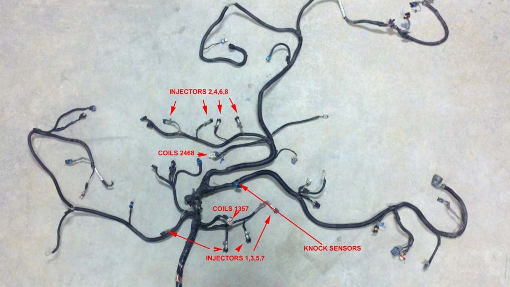
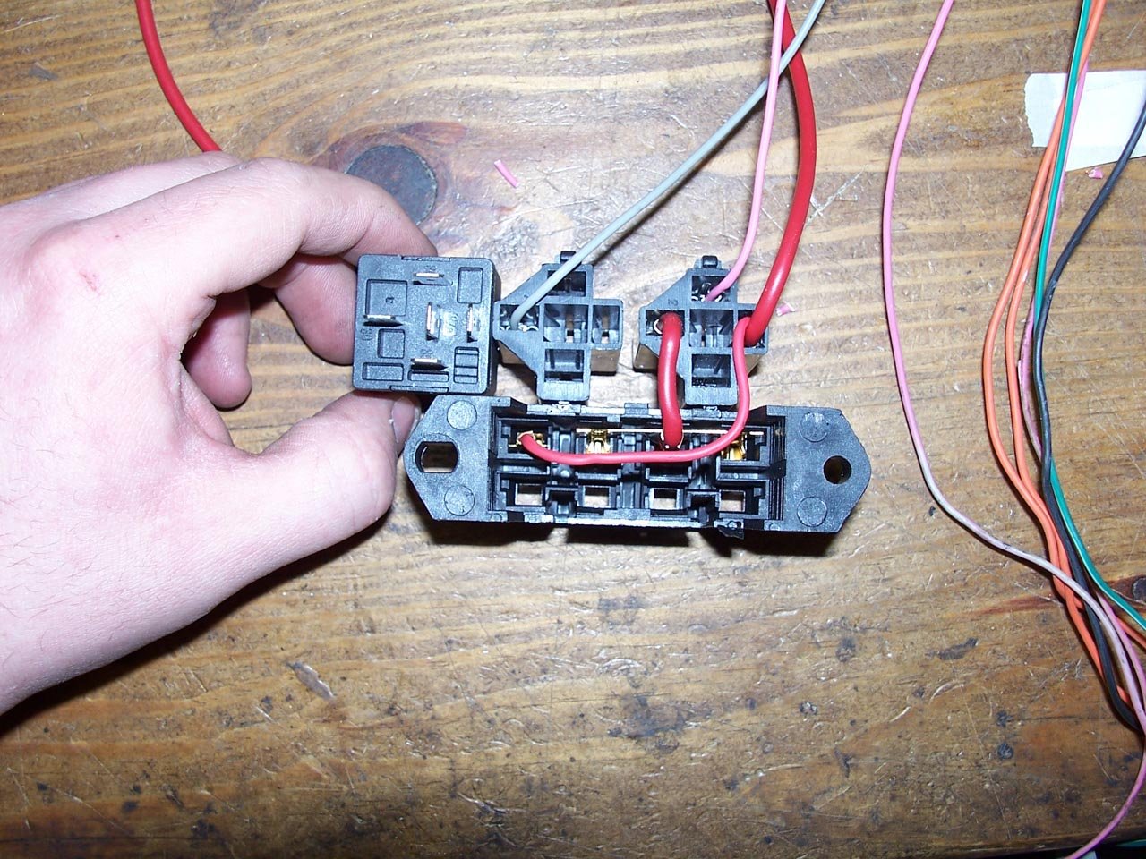
Here is some helpful information if you want to modify your stock truck wiring harness your self 1999-2007. This junction block is part of the main engine harness, that screws into the bottom of under-hood fuse block. If you want to use the whole fuse block you can, but I like to keep it clean, and wire a lot of these together. There are a lot of wires here. Each injector has its own power wire all the way to this block. All 8 of them can be wired together into a single fuse to clean things up. This is what is done inside the fuse block. Be sure to look at the pictures of the harness at bottom of this page.
The method I show involving removing wires from the PCM, removing circuits DOES NOT HAVE TO BE DONE if you don't want to. That is all to get a much cleaner look, and to simplify things later on if you have to troubleshoot anything. If all you want to do is make the engine run, you can take all the PINK wires at the C2 Fuse block plug and make them 12v+ key hot, get the two ORANGE wires and make them battery constant hot. Provide fuel pressure to the rails, turn engine over with starter, and it will run! This would be the most basic simple way to run. The computer has controls/outputs for fuel pump, check engine light, fans, tach, speedometer. There are signals for brake switch, tow haul, all of which are found in the connectors near the fuse block connector. I don't recommend just combining all the pink wires into one and powering it. You are asking for issues if there is ever a short, including melted wires, fire, so on.
How To Identify Your Vortec Truck Engine & Year - GM Made many changes years to years that can help pinpoint the actual model year of your engine takeout. Click for info.
Info for 2003+ Chevy Express Van harness - By Request, Express Van 6.0 Wiring harness info
Tach wiring for 99+ Vortec/LS1 - Tach not working on you're Vortec/LS1 engine, answer may be here!!
Air Conditioning - New 9/8/20! Everything to know about using your Gen3 PCM to control A/C on your 99-07 Gen3 LS Engine Swap.
Drive By Wire - Electric Throttle Control - Info explaining Drive By Wire and hooking up Cruise Control on Drive By Wire setups.
Drive By Wire to Cable Throttle Conversion - Use 03+ harness/pcm to go back to cable throttle control. Also, can use the 99-02 RED/BLUE connector PCM with some additional modifications. info inside!!
Underhood Fuse Block, 2000-2007 Pickup/SUV 4.8/5.3/6.0 - Using the stock Fuse Block from 99+ Vortec harness to power you're engine. 7/22/17 UPDATED
PCM Connector Pinouts 99-02 - PCM Pinouts for 99-02 BLUE / RED PCM connectors. Similar BETWEEN 99-2002. - Download Here!
PCM Connector Pinouts 03-07 - PCM Pinout for 03-07 BLUE / GREEN PCM connectors. Similar BETWEEN 2003-2007. - Download Here!
Injector Flow Rates & Mass Airflow Sensors - Info on injector size & usage, MAF types used in Vortec/LS1 based engines.
Fuse Block and OBD2 Port Wiring Information - Part#'s for parts to build custom fuse block/relay sockets, OBD2 Port.
Oxygen Sensor types information - Page about the different o2 sensors used, differences in wiring, and function.
1999-2002 Vortec Truck Harness Schematics - schematics for 99-02 truck harness
2003-2007 Vortec Truck Harness Schematics - schematics for 03-07 truck harness
4L60E to 4L80E Harness Conversion - This page will go over what is needed to make a 4L60E harness work with a 4L80E transmission
1993-2000 OBS/GMT400 to LS Gen3 (4.8/5.3/6.0) Swap Specific Info HERE! !!Updates for 93-95 9/17/2024 !! Info for wiring Gen3 LS into the the 93-2000 OBS Trucks. Pinouts, Pictures, Video!
Step By Step Harness Rework Procedures - Facebook Photo Album, Covers info to convert 99-02 5.3L harness to stand alone, similar on 2003+ as well. You can also download this in a PDF printable file with all my notes. Thanks Paul C. for sending these to me to share. Low Quality 3.5mb High Quality 11mb
You might check out this YouTube channel UCanDoIt2, has some very good videos going over harness modification as well.
Now adding videos to my YouTube channel LT1SWAP.COM . I've got a 3 part video on 2003+ wiring harness modification, complete start to finish.

If you want to run without the large under hood fuse block, following info might help to see which wires go where.
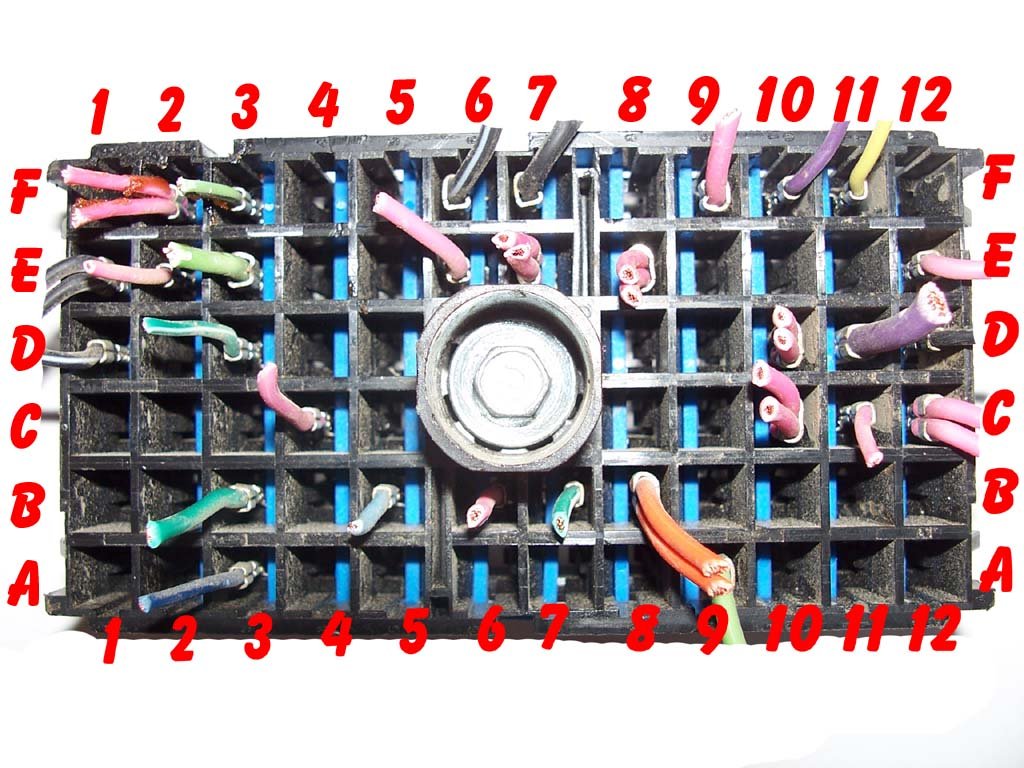
This is C2 - Underhood Fuse Block connector. This connector is part of Engine Harness. If you look closely on you're harness, this plug has the letters and numbers printed on the plug.
|
|
|
|
|


Click Year for Pinouts for Truck Harnesses. Some of the wires inside these links are made BOLD. This typically means this wire is needed or very useful in a stand alone harness setup. C2 information is in these links. Info is more complete for 1999, 2000. Later years should be similar, use circuit #'s to compair. 1999-2002 are VERY similar. Around 2001, the engines no longer had EGR, so that does away with 5 wires. The differences in the 99-02's don't matter a bit when making a harness stand alone. Very detailed info for what to remove, keep, etc is just a few lines down, I leave all this info so you can see changes year to year if you lik.
1999 2000 2001 2002 2003 2004 2005 2006 <-- these are right out of gm manuals. see below for detailed info.
Helpful tips for harness modification.
All the grounds needed will be in the engine harness. Should be a few of them. Rear of engine behind intake, should be two grounds. G103 & G104, behind accessory bracket is a ground. G102
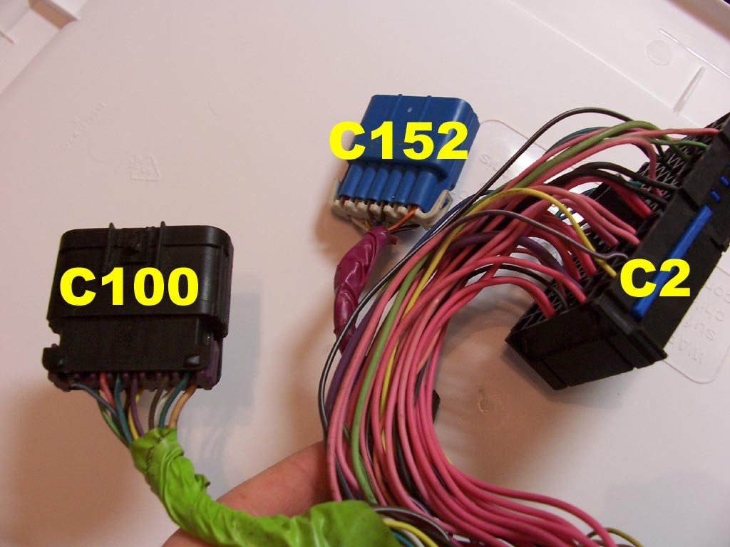
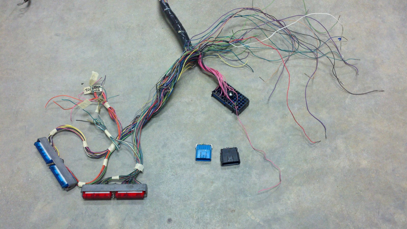
The very first step I do when modifying these Vortec harnesses, is cut all the wires on C100, C152, and cut all BUT the PINK from C2 Underhood. Next step is remove the pins from the PCM connectors you don't need, and label those you DO need. See pinout charts listed here for 99-02 or 03-07 I have color coded the PINS TO REMOVE and the PINS TO EXTERNAL CONNECTION (KEEP).
For 1999-2007!! here is a description of the wires from the PCM connectors that will connect to an external connection, outside the wiring harness. This is all you need for stand alone. (Includes Engine, Transmission) No Emissions.
----------------------------------------------------------------------------------------------
Blue Connector C1:
Pin 33 - Purple - TCC Brake Switch - This wire tells the PCM when you hit the brakes. It needs 12v+ all the time, and the brake switch should "open" this circuit when you hit the brakes.
Pin 42 - empty - Fan 1 Control - This will be empty on 99-2002 harnesses. A pin can be added for electric fan control. Programming will enable the fan control. PCM supplies a GROUND to turn on a relay. If you have two fans, keep reading, pin for fan 2 will be on the RED connector C2. You must wire your fans through a relay.
Pin 58 - Dk Green - Serial Data - This is the Class 2 Serial Data wire that goes to the diagnostic port (OBD2) pin 2.
Pin 19 and 75 - Pink - 12v+ KEY Power Source to PCM. Hot when Key is in the ON and CRANK positions.
Pin 20 and 57 - Orange - 12v+ BATTERY Power Source to PCM. Hot at all times.
------------------------------------------------------------------------------------------------
Red Connector C2: or GREEN
Pin 9 - Dk Green/White - Fuel Pump Relay Control - This wire the PCM supplies 12v+ to control a relay for fuel pump. PCM will turn on the fuel pump for 2 seconds at initial key on. When the engine cranks or starts, the fuel pump will then continue to run, untill the engine stops, or you shut off the key.
Pin 10 - White - Engine Speed Signal - Tach signal. Stock programming of the PCM will output a 4 cylinder tach signal. When I program the PCM, I can change this signal to a 8 cylinder. This way you don't have to modify your tach.
Pin 33 - Dk Green - Fan 2 Control - some 99-02 harnesses will have a pin here, this was used for the HVAC Recirculation Door control. The PCM would control the A/C recirculation to help cool the a/c system if it got too hot. In an engine swap, programming can be changed to let this control a second cooling fan. Again, PCM supplies a GROUND to run on a relay. You must wire your fans through a relay.
Pin 46 - MIL Control - This is your ''check engine'' light control wire. PCM will supply a GROUND on this wire when the light should be ON.
Pin 50 - Dk Green/White - VSS - This is a signal generated by the PCM, based on information it receives from the vehicle speed sensor located in the transmission. The PCM takes the sensor signal, and calculates the tire size, gear ratio programmed into it, and makes a 4000 pulse per mile signal. This is useful if you want to use a cruise control box. Some speedometers will use this as an input, others, like Autometer's, will hook directly to one wire of the speed sensor in the trans.
After pins are removed, AND some labeled, I start working into the harness to remove un-needed wires that are now removed from the PCM connectors. Some will pull right out, as they went to C100, C152, or C2 Underhood. Pull all the loose wires that go deeper into the harness back past where the original C100, C152 were located. Tightly tape up the wire bundle at this location, as to not let there be too little or too much slack on the wires going to the PCM. Be sure to use masking tape to hold the basic shape of the engine harness. As you progress into the harness, you will find some ground wires that trace back to splice packs. Simply cut the wire up close to the splice pack. Keep 1 or 2 ground wires for when you add the relays and diagnostic port, you will need a ground. DO NOT LET THE HARNESS FALL APART OR GET TANGLED. As I get up to where wires branch out, I will follow that branch out, remove any wires going into it, then tape that branch back up. Only doing one branch at a time.
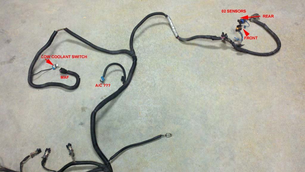
You can start to cut and label the pink wires from C2 Underhood. See this link and look for the wires highlighted in BLUE. You may find it easier to use a digital volt-ohm meter set to continuity beep mode, in finding where each pink wire goes. This is pretty standard across all Vortec 4.8/5.3/6.0 harnesses: PCM - 2 pink; MAF - 1 pink; TRANS - 1; COILS - 2; INJECTORS - 8; O2 SENSORS 1 EACH;
Taking apart a 2001 Vortec 5.3 harness....
|
|
|
|
|
|
|
|
|
|
|
|
|
|
|
|
|
|
|
|
|
|
|
|
|
|
|
|


.jpg)
.jpg)
.jpg)
.jpg)
.jpg)


.jpg)
.jpg)
.jpg)
.jpg)
.jpg)
.jpg)


.jpg)
.jpg)
.jpg)
.jpg)
.jpg)
Custom 5.3 Vortec harness, lets you place PCM 5 feet away from back of intake manifold. Clean layout. I either shortened or lengthened almost every wire in the harness for this modification.
|
|
|
||
.jpg)
.jpg)
.jpg)
The above harness installed in the vehicle.
|
|
|
|
|
|||
.jpg)
.jpg)
.jpg)
.jpg)
.jpg)