This page is going to outline what is required when converting from a Drive By Wire to Cable Throttle control. Most of the time I would see no reason NOT using the drive by wire, unless you simply don't have all the parts. With programming, throttle response can be made better with the removal of torque management. If you are dead set on CABLE throttle, then here you go. The info covered on this page pertains to the Gen 3 truck engines, 2003 to 2007 specifically.
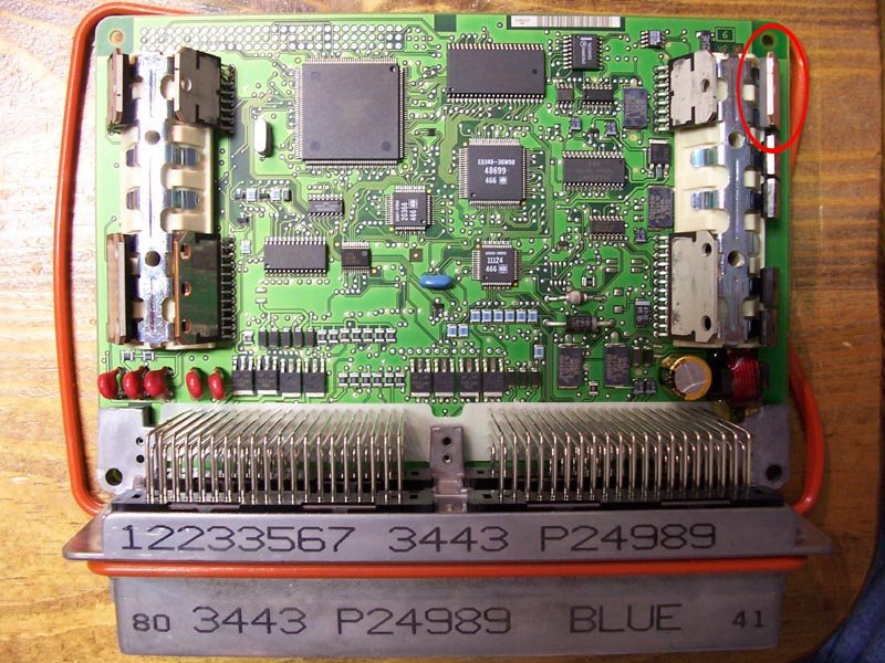
Drive by wire uses a separate module, called a TAC module. This module goes in-between the Gas Pedal and the Throttle Body. The TAC module communicates with the PCM via two dedicated wires. Other then that, and Power/Ground, The throttle body wiring and gas pedal wiring ALL go to the TAC module. So removing the Drive By Wire wiring is not too difficult. Pin 14,15 of the BLUE PCM connector are the two dedicated communication wires.
What makes things nice, is GM still used a Cable throttle body in the Express Vans with the 4.8/5.3/6.0L engines until 2005 and the GTO in 2004. To allow cable throttle, the PCM has to be able to control the IDLE AIR CONTROL (IAC) motor. This is simply a stepper motor. As the stepper motor turns one way or another, it opens or closes a valve, and controls air flow into the engine. I have identified the PCM's 2003-2007 that WILL SUPPORT the idle stepper motor required for Cable Throttle Control. (MOST PICKUP TRUCK PCM's DO NOT SUPPORT DBC) If your number is 1 digit off, it won't work.
1999-2002 Serv. No. 09354896, 12200411 - All BLUE/RED connector PCM will work with either drive by wire, or drive by cable, the PCM simply needs programmed correctly.
2003: Serv. No. 12576106 with Hwd. No. 12570558 - Most all 2003 trucks should have this PCM
2004: Serv. No. 12586243 with Hwd. No. 12583659 - Mostly GTO and Express vans got this PCM, as well as Caddy CTS-V. MIGHT be in trucks.
2005-2006: Serv. No. 12589462 with Hwd. No. 12589161 - I think you'll only find this in Express Vans. Maybe in some pickups.
2007: Serv. No. 12602801 with Hwd. No. 12589161 - Found only in Express Vans (even if the VAN was DBW, it supports cable throttle)
Also, a tip on finding these. Any 4.3L V6 Pickup or S10-S10 Blazer/Jimmy will have the above computer, and can be programmed for the V8 Gen 3 LS engine.
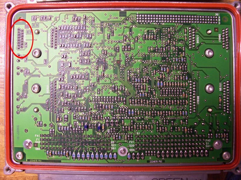
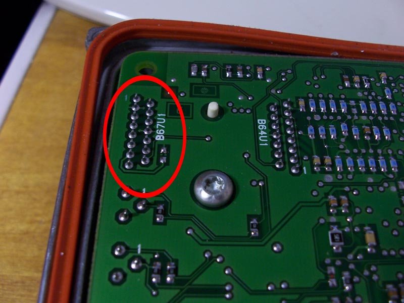
Okay. So there are some numbers to go off of. one final check to see if your PCM can support it, if its not listed here. Remove the cover of the PCM (4 torx screws). What you are looking for is if the chip that controls the stepper motor is there or not. Look for the pins sticking through the circuit board at the marking "B67U1". See pictures here: Removal of circuit board not required or recommended to check. I only did this to show you what is under those pins. The info above I've now used for a few years and is rock solid info.
|
|
|
|
|
|


Once you know you have the right PCM, I can program it for your application. You tell me the engine, trans, etc and I can fix you up. For those using 4L60E trans, I use a base Pontiac GTO calibration, and make changes to match your configuration. For those with a 4L80E trans, I use a base Express van calibration.
As for the wiring, you need to add wiring for the IAC motor and THROTTLE POSITION SENSOR (TPS). You can use the 2003+ Oil Pressure sensor plug as a TPS plug, (computer does not need to know oil pressure) You will need to find a IAC plug. Almost any older GM vehicle will have this plug, check local parts yard or maybe a parts counter can get a replacement plug. Typically the IAC has two light green, and two light blue wires, one each with black stripe and a white stripe.
Here is a chart that will show the wire color, description, and where the wire needs to go in the PCM plugs. The wire color and location shown match 2003+ express vans that had mechanical drive by cable throttle bodies. You CAN use the oil pressure sensor plug from a 2003+ harness for the throttle position sensor. Pay attention that the 5v ref and low ref are opposite between oil pressure and tps. If you use the oil pressure plug for tps, you need to do one or the other; switch the BLACK and GRAY wires at the TPS plug, or switch the BLACK and GRAY wires at the PCM. If you don't switch the black & gray, the TPS will work backwards. Finally move the Oil Pressure Signal wire (TAN/WHT) FROM GREEN 58 to GREEN pin 24.
Another note, the EXACT location the TPS gets its 5 VOLT REFERENCE from does not matter, it could come from pin 7 or 8. Same goes for the LOW REFERENCE, it could come from pin 60 or 63. What IS important is that the TPS has 5 VOLT REFERENCE and LOW REFERENCE at the correct locations at the sensor.
| WIRE COLOR / SENSOR PIN LOCATION | DESCRIPTION | PCM PLUG / PIN LOCATION |
| Throttle Position Sensor (FACTOR PIN LOCATION FOR 2003+ DBC EXPRESS VAN) | ||
| PIN A or 1 - GRAY | 5 VOLT REFERENCE | BLUE PIN 8 |
| PIN B or 2 - BLACK | LOW REFERENCE | BLUE PIN 60 |
| PIN C or 3 - DK BLUE | TP SIGNAL | GREEN 24 |
| Oil Pressure Sensor (2003+ harnesses) | ||
| PIN A or 1 - BLACK | LOW REFERENCE | BLUE PIN 63 |
| PIN B or 2 - GRAY | 5 VOLT REFERENCE | BLUE PIN 7 |
| PIN C or 3 - TAN/WHT | OIL PRESSURE SIGNAL | GREEN PIN 58 |
| WIRE - IAC PIN # | DESCRIPTION | PCM PLUG / PIN LOCATION |
| Idle Air Controller Valve | ||
| LT GRN/BLK PIN A | IAC COIL B LOW | GREEN PIN 77 |
| LT GRN/WHT PIN B | IAC COIL B HIGH | GREEN PIN 76 |
| LT BLU/BLK PIN C | IAC COIL A LOW | GREEN PIN 78 |
| LT BLU/WHT PIN D | IAC COIL A HIGH | GREEN PIN 79 |
If converting from DBW to DBC on a RED/BLUE harness, you only have to add the wiring for the IAC valve and TPS. Use this schematic for pin information.
If you have a RED/BLUE connector PCM, you CAN use this pcm on a 03+ harness (GREEN/BLUE connector) with cable throttle, with a few simple modifications. The only thing that needs changed, other then what was talked about above, is some of the oxygen sensor wiring. On the 2003+ blue/green connector PCM's, the PCM supplies a GROUND for the oxygen sensor heater's, and 12v+ comes from the fuse block. In the 99-02, power and ground is fed directly to the o2 sensor heaters. To make the changes needed to 2003+ blue/green harness, to work with a blue/red computer is this:
REMOVE: BLUE PCM connector pins: 24,27,64,67. These should all be black with white stripes. These were extra ground wires provided to the 03+ pcm so it could control ground to the o2 heaters. The 99-02 pcm does not need these. Just pull the pins out, don't cut anything yet, we need to hook these to a few other wires we pull out of the PCM connectors.
Next we need to remove the wires from the PCM connector that go to the oxygen sensor heater control. There are 4 wires, one for each oxygen sensor. If you are only using front oxygen sensors in you conversion, omit anything to do with Sensor 2.
Bank 1 Sensor 1 - BLACK/WHITE - GREEN connector pin 72
Bank 1 Sensor 2 - BROWN - GREEN connector pin 52 - after CAT o2 sensor
Bank 2 Sensor 1 - LT GREEN - GREEN connector pin 74
Bank 2 Sensor 2 - RED/WHITE - GREEN connector pin 53 - after CAT o2 sensor
Now, you should have 4 ground wires, and 2 (or 4) oxygen sensor heater control wires pulled from the PCM connectors.
You need to locate the 4 tan oxygen sensor low reference wires going into the BLUE pcm connector. If just using front o2 sensors, its BLUE pins 26 and 29. If also using rear o2 sensors, add pins 25 and 28. These wires will always be TAN and may have a white stripe. The easiest way I can think of to splice into these, is pull the pin out (REMEMBER WHERE IT GOES BACK) remove some insulation with a knife, solider on a wire, and slip some heat shrink up and past the terminal and shrink the heat shrink down over the splice. Then reinstall the pin in its original location. Leave about 12" of wire loose for each wire you splice into. Do this for all the o2 sensors you will be using.
So at this point. You should have 4 black/white ground wires loose. 2 to 4 oxygen sensor heater control wires loose, and 2 to 4 wires going to each of the TAN wires. All of these wires need hooked together in a big splice pack. First get some larger heat shrink, 1/4 or 5/16 should work. Put about 4 inch long piece of heat shrink over all 4 ground wires. Next strip off about 1-2 inches of insulation off all your wires. Start hooking them together end to end, you should be able to solider all these together, and slip the heat shrink over when done.
The last step, is to make the connectors fit inside the PCM. This will require cutting the rib off the GREEN plastic terminal cover, so it will fit in the RED pcm socket.
You will need to use oxygen sensors for a 2002 chevy truck, 5.3L, will be a white plastic connector, and will plug right into the 03+ harness without changing plugs.
That is it. To understand WHY we had to hook in the TAN wires, please read the OXYGEN SENSOR info page.
*****If you found this page helpful, please let me know, by all means. brendan@lt1swap.com